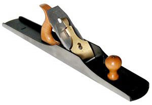
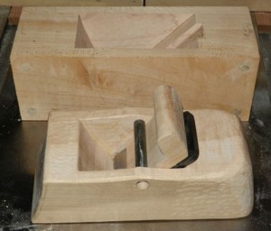
 I talk a lot about both setting up and using hand planes. Probably about 95% or more of my audience will either go to their favorite shop to buy a plane, or work to restore an old family heirloom or a garage sale find. There is another way to obtain a plane, and it brings with it the chance to hone some extra skills: Make a wooden plane. The majority of my personal planes are manufactured, but I did make a wooden plane about five years ago, and have made a couple more recently. For some reason, the thought of making a plane can seem pretty daunting, but most can make one successfully.
Now, there are really two types of wooden bench planes, in my opinion. One requires a bit more skill than the other. The first is what you’d likely find in workshops in the 1700s on into the invention of the metal hand plane (and even beyond for many). This plane type requires wood to be evacuated from the area that will become the mouth of the plane and up through the body. In most cases, the body of the plane retains most of its structure. The second, and in my opinion less demanding plane to make, is one where the wooden body is cut into three base pieces.
Two outside “faces” are removed from the center core. The center core is again cut into three pieces (toe, heel and a left-over that will make the wedge). By having the core separate from the other two pieces, you can easily use saws (table saw, band saw, hand saw…) to make the cuts establishing the “heel” piece which will create the bed for the iron, and on the “toe” piece, the curved relief opposite the bed, so shavings can easily be removed from the plane. The bed is what the iron rests on, while it is in the plane. Many bench planes utilize a 45 degree angle for the bed, as this is good for the majority of work. If you are working with very figured wood you can change this bedding angle from 45 degrees up to 50, 55 and even 60 degrees. It does become more difficult to push a plane that is bedded at these higher angles, but they do an outstanding job of handling some of the most figured woods.
The wood for the body should be a dense hard wood. There are many different types of woods that can be used, so it’s basically up to the maker. You can make a plane out of 8/4 wood, with the thickness of the wood as the maximum height of the plane, or you can laminate any thickness of wood where the wood thickness is now the width, rather than the height. This provides more flexibility in the design phase, removing the body height limitation you incur with non-laminated wood bodies, while also keeping the cost down as thicker wood blanks (10/4 and thicker) usually command a higher cost. One last thing to remember, relating to the wood grain, is you want the grain running from the toe down towards the heel.
Before you make any cuts, I like to drill holes for alignment dowels, in the four corners of the plane blank. These will allow you to get the pieces back into their original orientation when you are gluing up the pieces, after you’ve cut the blank into the required pieces. The next step is to do some layout. For this stage, it is best if you already have the iron you will use in the plane in your possession. This allows for direct measurement, so things actually fit together after the glue-up. Measure the width of your iron, and then add on between an 1/8” and 1/4”, so you can adjust the iron slightly when setting the plane for work. Center your measurement on the plane blank. Mark lines down the length of the plane, as reference, before beginning your cuts. One reminder, always cut on the outside of your line, as any material removed from the center section could diminish the available adjustability, or even send you to the grinder in order to remove metal from the iron so it will fit the opening.
Next is cutting the center section into the three sections. First, choose the angle you want for your iron. Mark the angle on the outside edge of the center core, with the angle intersecting the sole about a third or so back from the toe. This cut can be done on a table saw, which can leave a glass smooth surface, or you can use whatever means are available to accomplish the same end results. The other cut line is to a slight arc, coming up from the sole with enough angle so you can reach in to get out shavings. There is nothing hard and fast about which angle you choose. I chose between 60 – 70 degrees, but you can try some different, if you wish. This second cut, since it is a curve, is best made with a band saw, or something else that can handle the curvature. Remember to keep the extra “triangle” piece, for your wedge, and it also comes in handy to back up the side walls when drilling the hole for the cross bar.
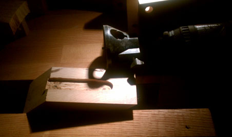
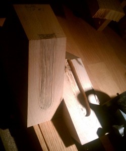 Next up is removing material on the bed of the heel piece, so the screw for the chip breaker has enough room for the iron to sit flat on the bed. Measure the screw head and then mark out with a little buffer added on, centered on the bed, from the top down to about a half-inch or so from the sole. This will give you enough range so your plane will function for a long time, even after many many sharpenings. I used my dremel, with a flat bottom bit, to remove the necessary material. I did use one of the attachments that allow the dremel to work much like a mini router, so it kept the depth of cut consistent.
Join us here tomorrow to read the rest: I’ll talk about the process for gluing up and finishing my homemade wooden plane!
This is Part one of a two-part post. To continue to Part two, click here.
Lee Laird has enjoyed woodworking for over 20 years. He is retired from the U.S.P.S. and works for Lie-Nielsen Toolworks as a show staff member, demonstrating tools and training customers.
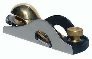 Many of my customers have come to me, wanting advice on which of our many block planes they should buy. Often this is prefaced by the fact they want to know this plane will provide a great deal of functionality, as this may be the only plane they purchase. With that in mind, I often suggest our Low Angle Rabbet Block Plane. When you first see this plane, you’ll notice it looks a little bit different from the majority of our other block planes. Just in front of the bronze cap, there is metal (on both sides) in the shape of what almost looks like a half circle. Since the blade on a rabbet plane reaches the full width of the plane (plus about .005”), this unique structure is the most efficient way to attach the front section of the plane.
 Most people know whether or not they live in an area where rust forms quickly. Many times the areas with elevated rust are near a body of water (ocean, lake, pond…), but high humidity alone will facilitate the formation of Mr. Rust. Obviously (or not so obviously), the bodies of planes made from bronze do not rust, even though the blade is still a potential target for rust. This is because rust is iron oxide. The metals used in most non-bronze planes, however, are subject to rust. This includes the blade, which is made from steel. Woodworkers will try a multitude of procedures to ward off rust. In our show kits, we will put Jojoba oil onto a rag (Ed. note:
  When we finally closed our gaping mouths, we got out our ultra-flat granite plate and a couple of
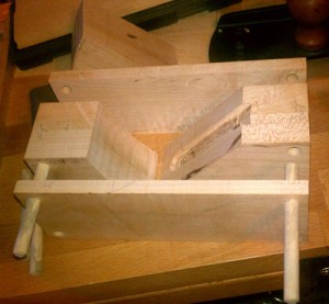
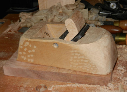
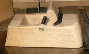 Now it’s time to cut your plane into your desired shape. Remember, it’s a good idea to have the back of the plane iron at least slightly above the top edge, so it’s easier to set or adjust the iron. After cutting to shape, you can use rasps, files, chisels, sandpaper, and anything else you desire to finish your plane’s surface the way you like. Some prefer a very smooth outer surface, where others like it to have texture so it’s easier to hold onto. This is personal preference. I usually use a chisel to put a bevel on all edges, so they are both stronger and feel better to the hands. If you don’t feel comfortable with this, sandpaper will knock off the edges, too. Now that the shaping is completed, you’ll need to make a wedge out of the left-over triangular piece. The fitting process can take a while, but it is another skill learned. Slide the cross bar into place, put the iron onto the bed and then put the wedge between the cross bar and the iron. Tap the wedge with a little force, so the cross bar marks the wedge where it makes contact. This will show you which portion is making contact, and which area is too low. Use your preferred method to remove material from the area on the wedge where it made contact. Reinsert the wedge, and repeat until the wedge is showing signs of contact with the cross bar, all the way across, or at least on both edges. (If it is making contact on both edges, it will apply equal pressure across the iron) It’s a good idea to work the fitting until the wedge reaches down past the cross bar about an inch or an inch and a half. Remember to take the fitting process slowly, as you can always remove more, but it’s more difficult to add material to the wedge.
 I talk a lot about both setting up and using hand planes. Probably about 95% or more of my audience will either go to their favorite shop to buy a plane, or work to restore an old family heirloom or a garage sale find. There is another way to obtain a plane, and it brings with it the chance to hone some extra skills: Make a wooden plane. The majority of my personal planes are manufactured, but I did make a wooden plane about five years ago, and have made a couple more recently. For some reason, the thought of making a plane can seem pretty daunting, but most can make one successfully.
 Next up is removing material on the bed of the heel piece, so the screw for the chip breaker has enough room for the iron to sit flat on the bed. Measure the screw head and then mark out with a little buffer added on, centered on the bed, from the top down to about a half-inch or so from the sole. This will give you enough range so your plane will function for a long time, even after many many sharpenings. I used my dremel, with a flat bottom bit, to remove the necessary material. I did use one of the attachments that allow the dremel to work much like a mini router, so it kept the depth of cut consistent.
